Construction
Due to the overall size of the project construction took roughly 24 man hours to complete. All of the machining was done personally, all of the welding was done by either Matt Burvee or Stefan Schacht.


The process started with cutting and cleaning all of the steel square tubing into the requisite sizes. Later this same saw would be used to cut the ACME threaded rods to size.
All of the pieces were laid out to show the raw materials for the project.
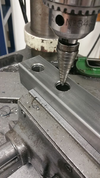
A large number of holes were drilled into the steel square tubing, first with a 1/4" drill, then with a step drill on one side. This was done so that short bolts could be used in the final assembly, and the nuts would reside on the inner portion of the square tubing. The larger holes were nessecary to allow access with a standard ratchet to tighten the bolts.


These two pictures show the brackets that were used for the table rest. While these are intended for use with wood, when using flat head bolts, the taper on the brackets themselves gave extra support to the bolt load. The offset nature of the holes in the bracket also served to locate the tubing to a greater degree than if they were patterned straight.


This view shows the hole and slot that were machined onto one of the central beams of the stand, these are used to create the angle of contact necessary for the timing belt pulleys, as well as to act as a belt tightener if need be.
The next process involved welding the stand together. These are after production shots. These welds were done with GMAW. The stand involved squaring up the central beams as well as the legs as much as possible and then tack welding before doing the final welds. The overhanging beam was the most troublesome to square up, but the process to do so was the same as the rest of the chassis stand.


Getting the ACME threads inside of the two pulleys proved to be the most interesting and largest hassle. First option was going to be machining the thread into the pulley itself. This however was going to require special tooling which would either have to be made in house, a skill that was not readily available, or special tooling was going to have to be purchased, which was not in the budget.
On the suggesting of one of the mentors that I was working with, the option of buying the correct ACME threaded bolt and then machining the pulleys in such a way as to affix the bolts inside of them came to be the best solution.
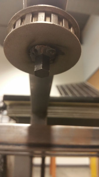
Even after this was determined to be the solution that was going to work best the challenge of fixing the bolts into the pulleys remained. The first thought was to set up the pulleys on a milling table and then machine a hex into each of them so the bolt flats would rest against the hex and could then be welded in place. This machining was going to leave the walls of the pulley too thin to be useful as a welding surface and another option had to be thought up. What ended up being done was each bolt was put onto the manual lathes with an emergency mandrel machined to hold the bolts tightly, then machine off the hex portion, leaving just a cylinder with the thread inside.
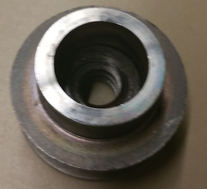
Then take each of the pulleys and then drill and bore out the small inner hole to a size that would accommodate the new cylindrical nuts. This machining, and the bold inside of the machined pulley can be seen above.
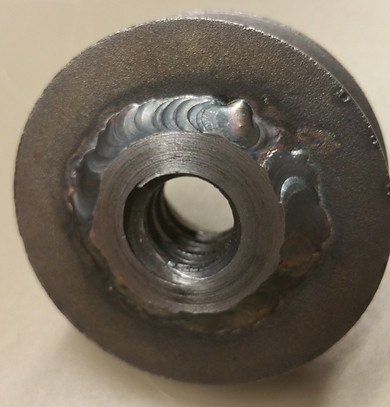
After the pulleys and nuts were machine to fit into one another they were taken to the welding lab. The original design called for each pulley to have two of the nuts inside of them, one sitting flush, and the other sitting a small distance outside. When the welding was done, the nuts were screwed onto a piece of scrap ACME threaded rod to make sure alignment would match across the two bolts. These parts used GTAW as the material of the pulleys was slightly questionable as to its degree of weldability being make of sintered steel, GTAW offered more control of the weld pool, as well as when filler material needed to be added to make the weld sufficient.
The first thing that was noted after tack welding both sides of one of the pulleys was that the thread had bound. It was almost to the point where the pulley could not be turned on the rod at all. Fortunately it was able to be twisted off, the welds ground off, and one of the nuts taken out. Many different configurations were attempted, between just tack welds, one side being fully welded, and then the other being just tack welded. There were no times where with both nuts being welded to the pulley that the thermal expansion of the metals allowed for the thread to stay aligned. Due to this unfortunate turn of events only a single nut was able to be mounted into each of the pulleys. Fortunately even with only a single nut inside of each pulley the chassis was able to meet specifications for applied weight.

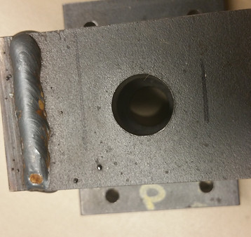
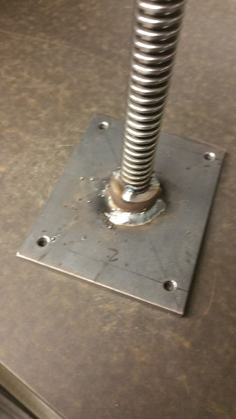
This part was to be used to locate the ACME threaded rods in the X and Y axis, and limit the pulleys in the Z axis. The bottom plate was drilled prior to welding. The center hole was done after welding to insure hole concentricity for alignment of the rod.


Three processes were done for the driving gear of the timing belt system. First a 1/2" rod gathered and then using a vice which had a hex assembly to the back of it, a hex was able to machined onto the rod which would be the grasping point for anything that would drive the system, be it a ratchet or power drill. Then the rod was welded into the third pulley. The rod then had retaining ring groves machined into it which was then set into overhanging arm of the stand.


The final portion of the timing belt system was to install rollers to control the belt contact angle and tension. For this a 3" fully threaded bolt was used, with a washer on top to prevent the belt from slipping off, as well as a nylon spacer to act as the roller itself. The two bolts would be used to clamp the roller into place on both sides of the tubing, as shown on the right.

The last parts to be manufactured were the parts to bring the three disparate elements together. The ACME rods, utilizing the unused bolts, were welded to plates which spanned the distance between the center supports of the table rest, and would be bolted to the stand later. The feet plates first had a hold drilled through them, which then had the bolt inserted and welded. After the bolt was fixed to the plates, the plates were welded to the stand so that the feet would be able to be attached.

Fully assembled table, with timing belt system in place and tightened. Of interest, with the length of timing belt used (90 inches), the tightening roller did not have to be taken past it's max extension to have the belt be functionally tight.